Leave Your Message
Choosing the right Cold Forging Die begins with the part, not the catalogue. Start with the workpiece alloy, its strength, the reduction per operation, and the press capacity. Then examine the required dimensions, production volume, lubrication, and expected tool life. A small change in corner radius can shift metal flow and raise local stress. Small details matter.
Professor Taylan Altan, a recognized forging researcher, has contributed extensively to forging-process and tooling research. A practical paraphrase of his technical guidance is: “Design the die around the material, forming sequence, and press—not hardness alone.” This is a paraphrase, not a verbatim quotation. It reflects an important selection principle: high hardness may resist wear, but toughness and resistance to fatigue also matter. A die that looks robust on a drawing can still fail early if its geometry concentrates load.
Industry data offers useful context, but not a shortcut. World Steel Association’s World Steel in Figures 2024 reports that global crude steel production reached about 1.89 billion tonnes in 2023. That figure signals the scale of metal production; it does not identify the best die material or predict service life. Those decisions require part-specific engineering and, ideally, production-trial evidence. Track cracks, wear, dimensional drift, and maintenance intervals. A shop-floor choice can seem obvious until a tiny radius starts cracking. Sometimes the first selection is only a hypothesis. This guide explains how to compare die materials, geometry, coatings, and operating conditions, while recognizing that actual performance depends on the complete process.
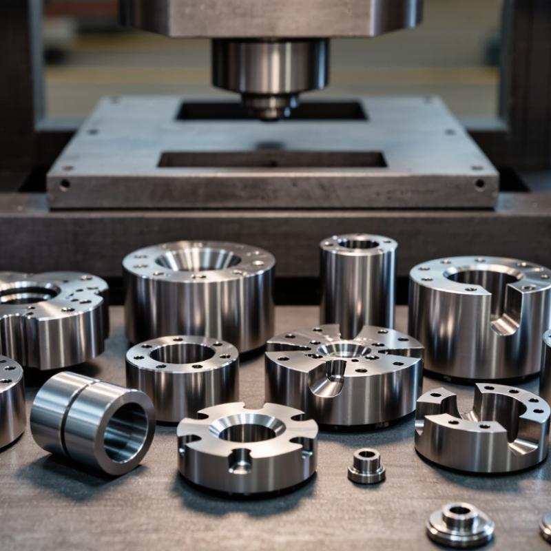
A cold forging die is not merely a cavity; it directs metal flow under repeated pressure. Its geometry influences filling, dimensional accuracy, surface quality, and the risk of laps or cracks. Small details matter. A slightly misaligned punch can leave uneven wear, while poor lubrication can mark a part and accelerate die damage. The right die therefore depends on the material, reduction per stroke, press capacity, and required tolerances—not just the part drawing.
The World Steel Association’s World Steel in Figures 2025 reports 1,882.6 million tonnes of crude steel production in 2024. That figure describes industry scale, not die performance, but it highlights the value of consistent forming. For a practical selection, review expected contact stresses, die-steel toughness, heat treatment, and access for inspection. Ask how the tool will handle corners and thin sections; those areas often reveal flow problems early. A polished simulation may still miss real friction or alignment variation. That uncertainty deserves attention. Trial runs, wear checks, and measured sample parts help confirm whether the die works as intended.
| Selection Factor | What to Assess | Typical Choice or Consideration | Why It Matters | Practical Check |
|---|---|---|---|---|
| Part geometry and operation | Part shape, reduction per stage, material flow, and whether the process uses upsetting, extrusion, or a combination of operations. | Use a die design suited to the forming sequence; complex parts may require multiple stations or forming stages. | Die geometry controls metal flow and helps limit folding, cracking, and incomplete filling. | Review the part drawing and forming sequence with a process engineer before finalizing the die. |
| Workpiece material | Material grade, strength, ductility, surface condition, and lubrication requirements. | Match die material and surface treatment to the workpiece and its forming load; harder or less ductile stock can increase die stress. | Workpiece properties affect forming force, wear, and the risk of galling or cracking. | Confirm the material specification and condition, including any annealing or pre-treatment requirements. |
| Die material | Required balance of compressive strength, toughness, wear resistance, and resistance to chipping. | Common options include cold-work tool steels such as D2-type or M2-type steels; carbide may be considered for demanding wear applications. | No single material suits every application: high wear resistance may come with greater sensitivity to impact or edge damage. | Compare expected loads, production volume, failure history, and available heat-treatment controls. |
| Die structure and support | Insert dimensions, shrink fit or other retention method, backing, and housing rigidity. | Use a properly supported die assembly designed for the press load and the die material’s strength and toughness. | Good support helps manage tensile stresses and reduces the risk of insert cracking or die movement. | Check assembly tolerances, preload or interference requirements, and alignment with the press tooling. |
| Surface finish and coating | Contact surface finish, friction, lubrication compatibility, and the workpiece’s tendency to adhere to the die. | Specify a suitable polished or ground finish; consider a surface treatment or coating only after checking process compatibility. | Surface condition affects friction, galling, material pickup, and the quality of the formed part. | Inspect the working surface and evaluate lubrication and any coating on trial parts. |
| Production volume and service life | Expected output, acceptable maintenance intervals, changeover time, and the cost of unplanned downtime. | For high-volume work, prioritize repeatable manufacture, replaceable wear components, and a documented maintenance plan. | Die life influences cost per part as well as production stability and delivery reliability. | Track parts produced, wear patterns, dimensional drift, and the cause of each die repair or replacement. |
| Press and process conditions | Press capacity, stroke, speed, alignment, lubrication delivery, and operating consistency. | Select and size the die for the actual machine and process conditions rather than press capacity alone. | Misalignment, inadequate lubrication, or inconsistent operation can shorten die life even when the die material is appropriate. | Verify load estimates, tool alignment, stroke settings, and lubrication at the production rate. |
| Inspection and maintenance | Critical dimensions, wear limits, inspection frequency, and available refurbishment methods. | Define measurable acceptance limits and a maintenance schedule before production begins. | Early detection of wear or damage can prevent defective parts and more extensive tooling failures. | Record die dimensions and surface condition at defined intervals, and inspect after abnormal loads or process changes. |